Stitching together video from multiple overlapping cameras can provide both wide field of view and high resolution compared to a single camera viewing the same total region.
During the development of multi-camera video systems for and for several clients and for internal ReliaSolve projects, the following solutions have proven useful.
Synchronization
When the camera system is moving or viewing scenes with moving objects, differences in the frame timing between even high-speed cameras cause tearing at the border between cameras. This happens both for global-shutter and for rolling-shutter cameras. Many cameras have an external hardware synchronization input that can be driven either by one of the cameras or by an externally-supplied common synchronization signal. Software triggering, though less reliable, can be used for some other cameras.
Rotation to align scans at rolling-shutter edges
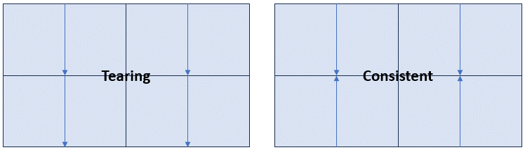
When cameras are tiled, the natural choice is to align all cameras with the same viewing orientation, all with their top edge facing up. For global-shutter cameras, this works fine. For rolling-shutter cameras, this causes a time difference at their edges, where the last line scanned on a camera in one row of cameras is next to the first line scanned in the the camera on the next row down. This produced local unsynchronized borders even for synchronized cameras, causing tearing.
By rotating every other row of cameras, the top and bottom sides of each pair of rows line up, making them scan at the same time. Although there will still be motion artifacts (shearing and/or stretching of moving objects), this removes the temporal gaps at the edges, removing the tearing.
This requires flipping the video on some of the cameras during stitching, but this can be trivially handled as part of geometric calibration that had to be done for edge matching in any case.
Mirrors for truly common centers of projection
Multiple cameras in a common system cannot physically overlap with each other. This requires either pulling them backwards along their principal rays or pushing them forwards along their principal rays. In either case, this keeps them from sharing the same center of projection. This means that objects at different depths seen by a neighboring pair of cameras experience different degrees of parallax, making it impossible to properly stitch the cameras at all depths. This causes tearing or gaps as objects move towards and away from the cameras.
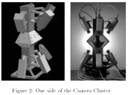
Majumder, A. S. (1999). Immersive teleconferencing: a new algorithm to generate seamless panoramic video imagery. MULTIMEDIA ’99: Proceedings of the seventh ACM international conference on Multimedia, 169-178.
Figure 2 from the above paper is shows an approach that uses mirrors to make the virtual centers of projection of two 360-degree rings of cameras the same between neighboring cameras. This makes objects at the edge seen by neighboring cameras remain at the same relative pixel location no matter how far they are from the camera, removing the tearing caused by objects as they move in the scene. Because of the finite apertures, the fields of view slightly overlap between cameras to enable gap-free blending.
The optical engineer will complain that the addition of a front-surface mirror provides slight distortions in the optical wave fronts. However, most high-resolution video sources must be compressed before sending them and the color and position errors caused by compression can easily exceed artifacts caused by mirror imperfections.
Rotation to optimize field of view
The mirror approach shown above has a limitation that only two rows of cameras can be tiled. This restricts the vertical field of view to twice the individual camera’s vertical field of view. Most cameras have a wider horizontal field of view than their vertical field of view. By rotating each camera 90 degrees, the horizontal field of view becomes the vertical field of view. Adding more cameras to the circle fills in extra pixels needed to cover the entire horizontal range.
This same approach can be used even without mirrors to minimize the number of cameras required to cover a given total horizontal and vertical field of view.
This requires rotating the video on all cameras during stitching, but this can be trivially handled as part of geometric calibration that had to be done for edge matching in any case.